Pocket Counter
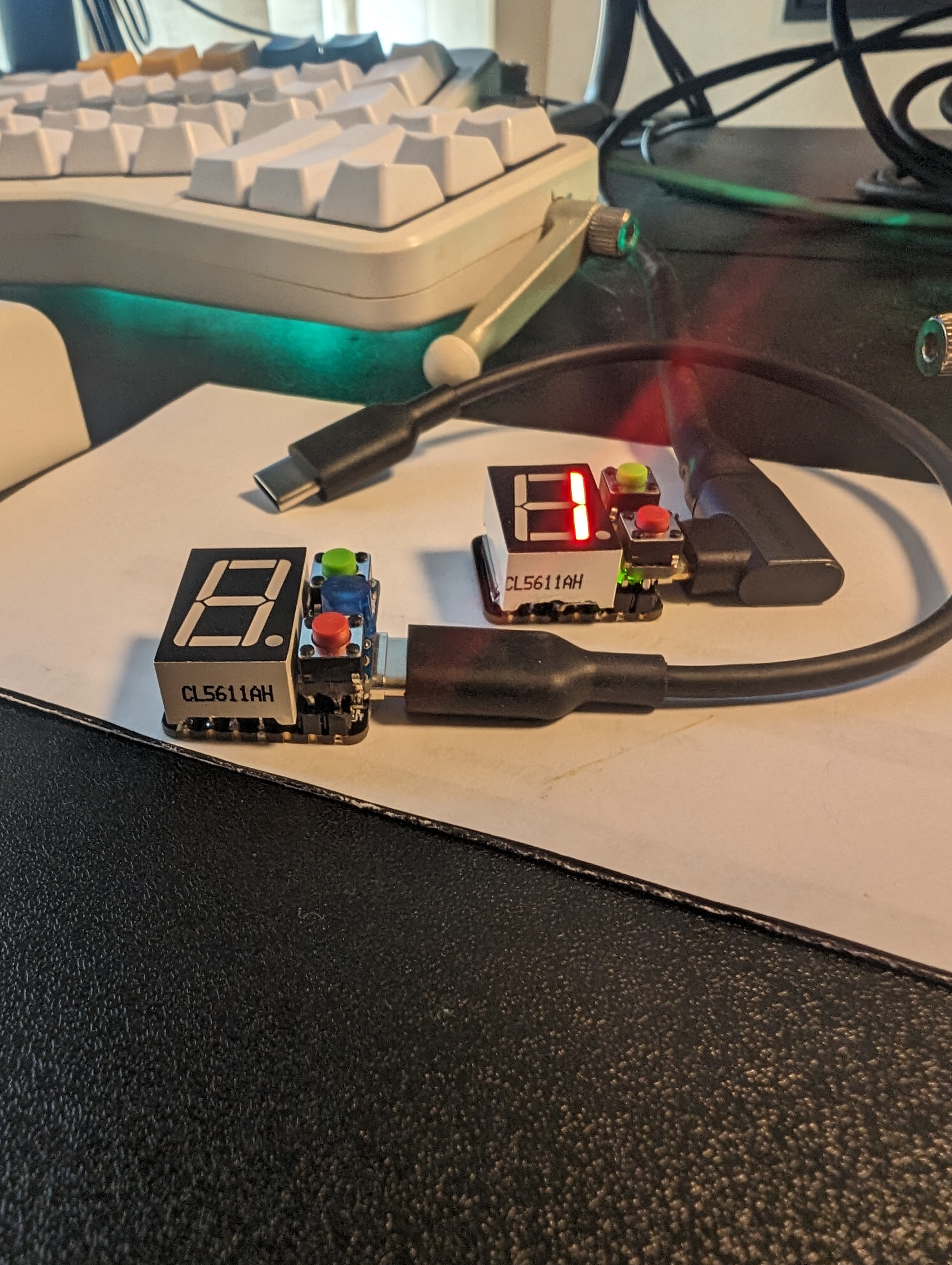
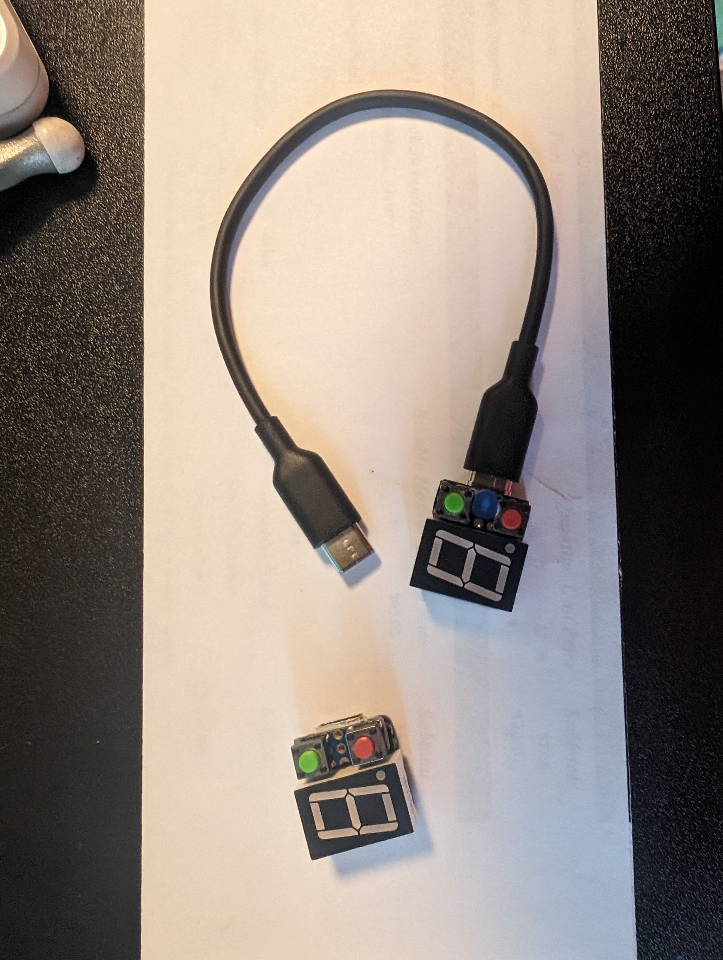
I made a small little counter/stopwatch with a microcontroller and an 8-segment display. I had some microcontrollers laying around and noticed the number of pins and physical size perfectly allowed an 8-segment display, two buttons, and a status LED. I came up with a little project with a satisfying form factor.
I decided it would be a good idea to keep some microcontrollers around the house. When I ordered a PCB for my Washing Machine Project I ended up with a handful of 8-segment displays (See the Washing Machine Post | See the PCB Post).
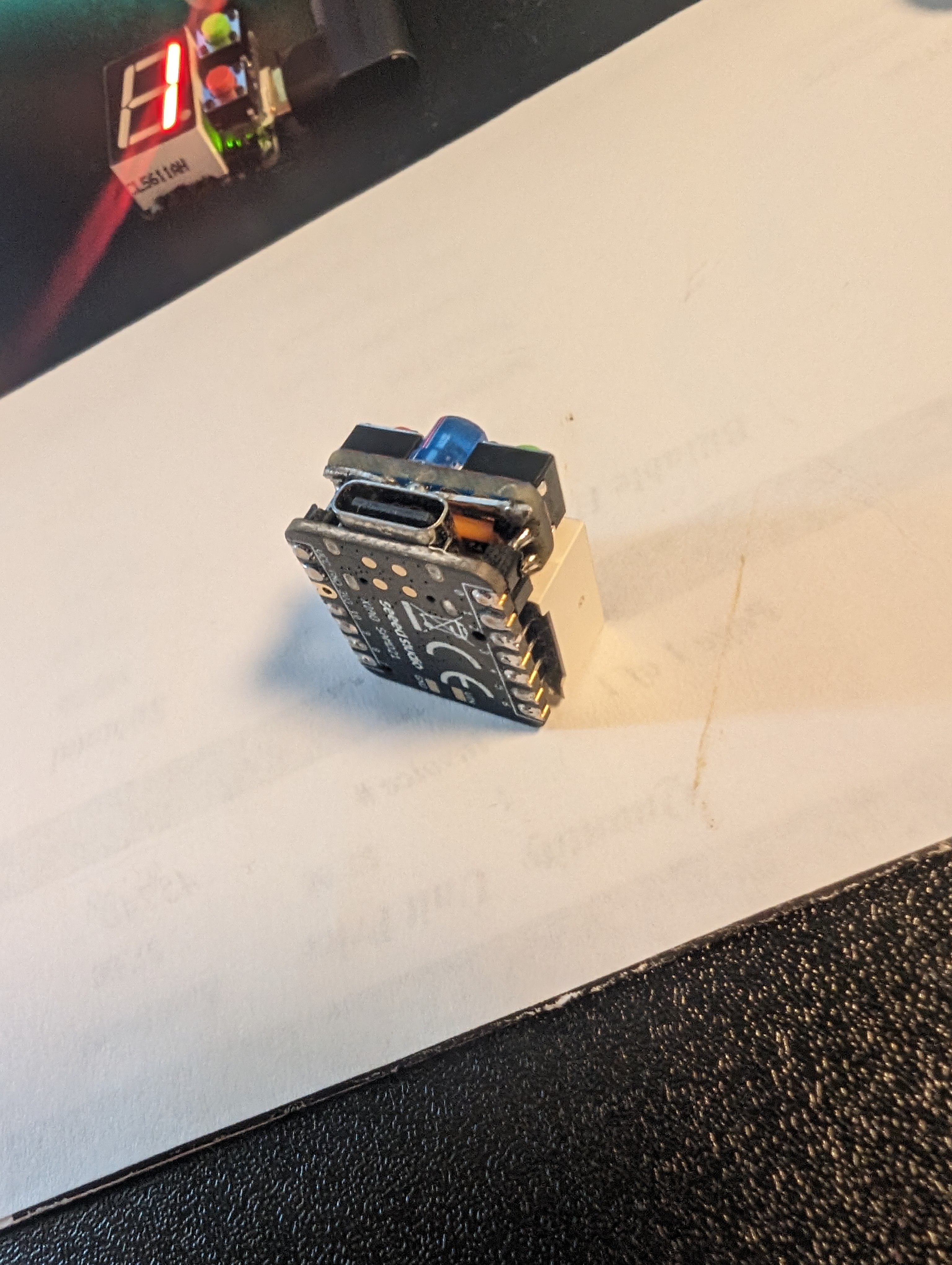
With the microcontroller and LED display sitting on my desk it finally clicked that the pin dimensions are nearly identical. The LED has two ground pins and only needs one. So if I cut one I can free up another GPIO pin. With pins 0/1 free I was able to tightly fit a small PCB next to the LED to fit two buttons.
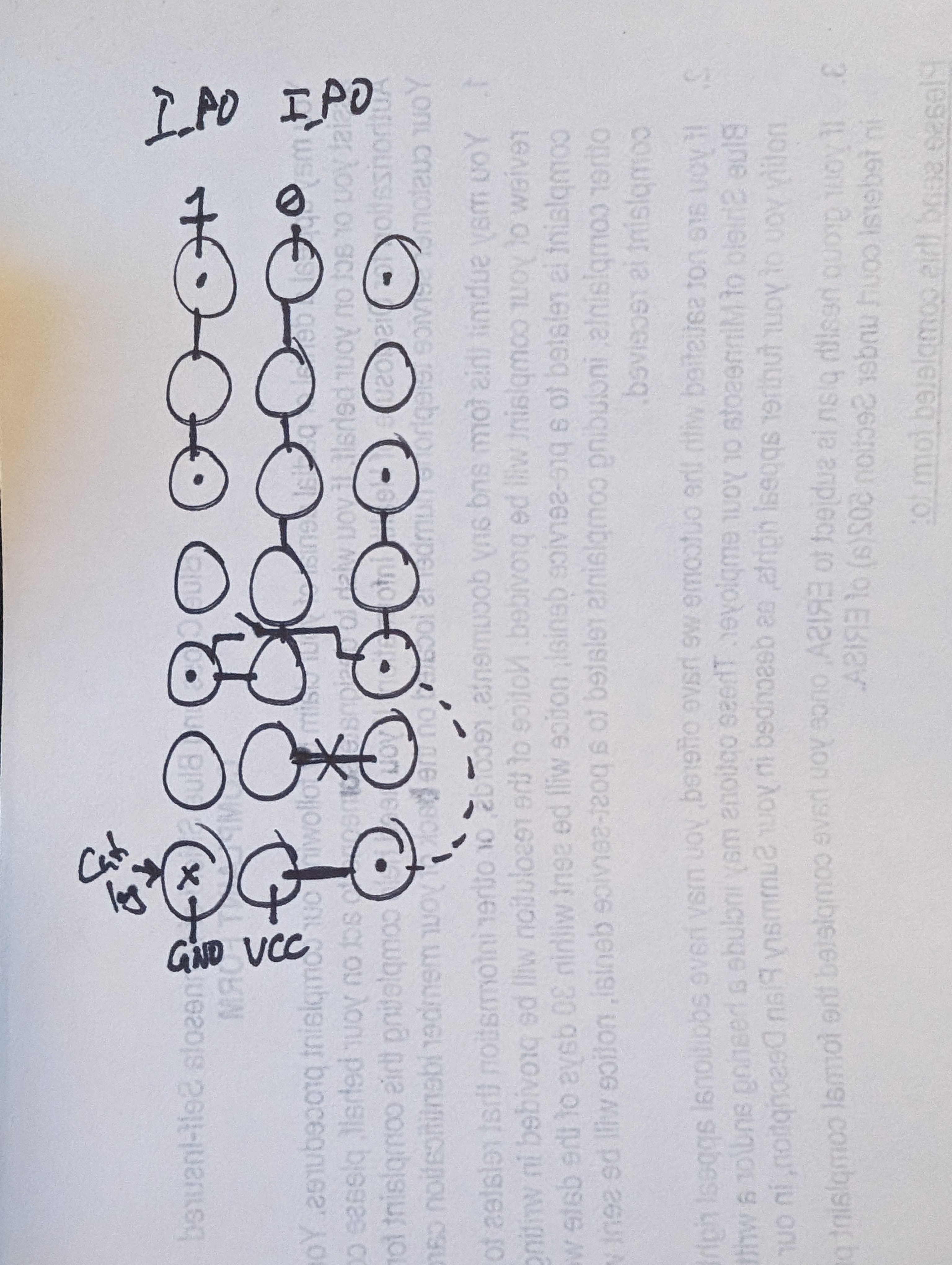
To fit the wiring on the PCB I had to do a little planning and cutting the default traces on my breadboard PCB I used.
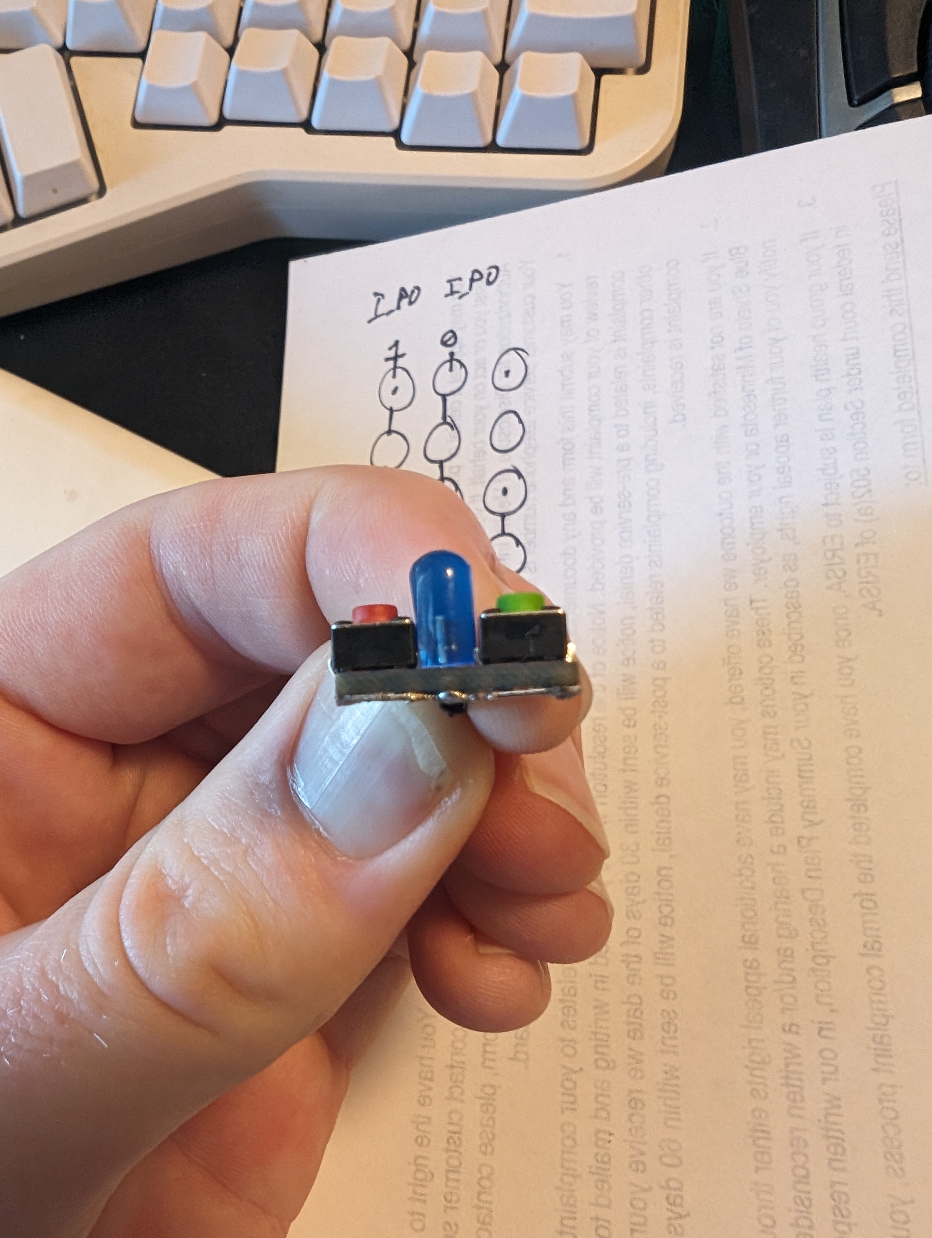
I didn’t think about removing the 2nd ground pin on my first prototype. I tried to pull the pin out without desoldering the entire microcontroller and ended up messing up the pad - so v1 doesn’t have the LED which v2 got.
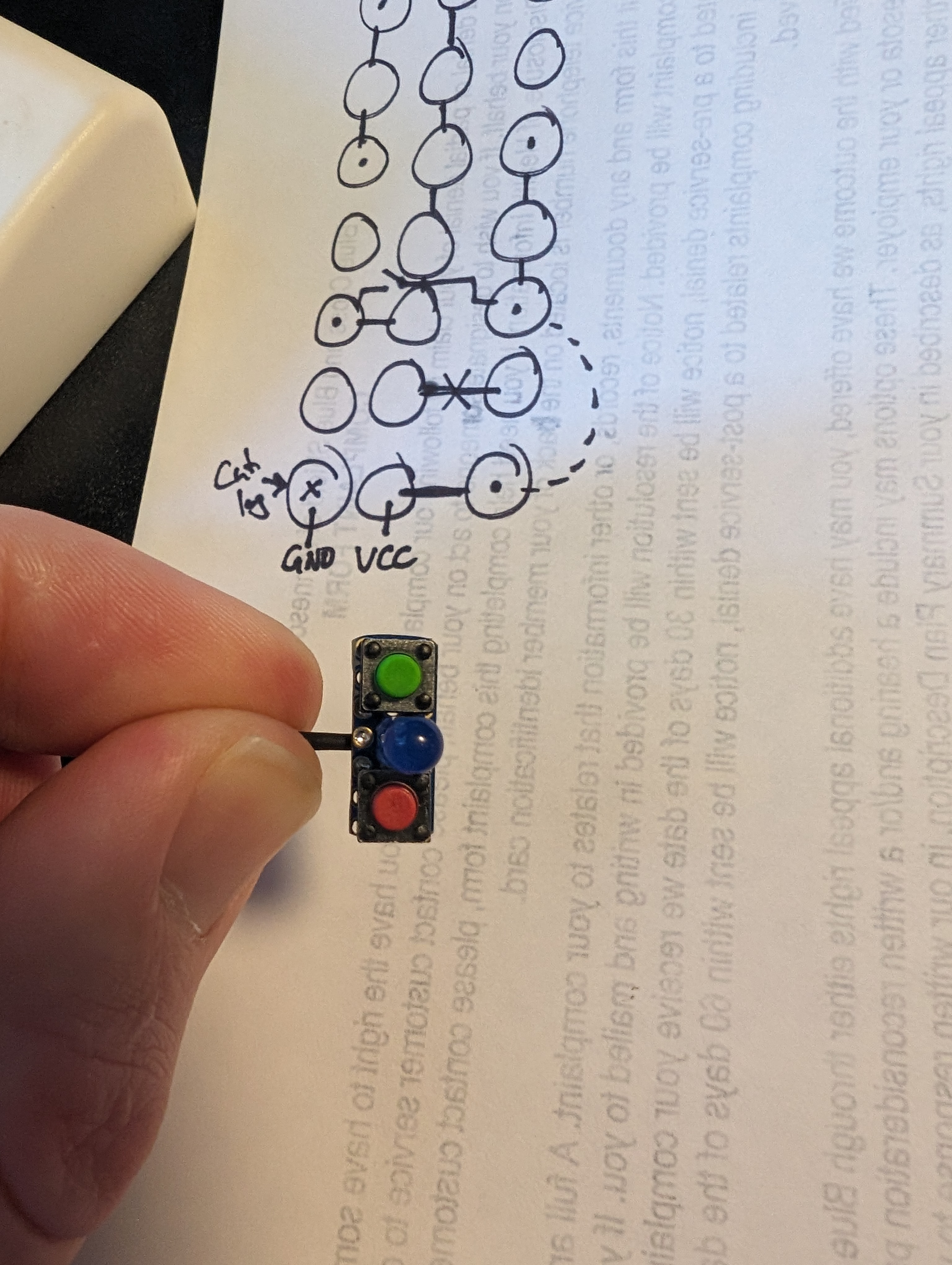
I originally made a simple counter. Green to increment, red to decrement, hold both to reset to 0.
In version two you can power on the device with the green button held to start in “counter” mode. But otherwise it boots into “stopwatch” mode.
In stopwatch mode the green button starts the timer. Red pauses. While paused green will resume and red will reset. (I didn’t implement a lap function).
When using counter mode I write the value to the flash memory so you can power off the counter and keep your value when powering back on.
They nicely connect to my phone with a short usb-c to usb-c. My phone powers the device but doesn’t seem to otherwise “notice” they’re connected.
Overall it has been a fun little challenge for my soldering and some basic programming skills. Since I’m working with a one-digit display and needing to print the time accurately once per second there were a few hurdles to figure out.
I try to predict how long I’ll get to display the time (maybe 950ms?). Then I calculate the “flashes” I add when I show the same number twice (22 needs to look like “2 2” and not “222” or you won’t know the difference between 2 and 22 and 222). The flashes are 50ms. For a days/hours/mins/secs separator I display a dash ‘-‘. And need to add that to the calculation. Then I divide the number of chars from 950 and display each char the correct amount of time. At the end of the loop I calculate how long the loop has lasted and delay the appropriate amount of time to get to the next second.
If I had multiple digits I could let the loop run as fast as it wants and just output the “current” count instead of trying to force a 1s loop like I am now.
I also considered trying to build an output buffer for the time and calculate which number in the buffer I should be displaying based on the current sub-second time. This would keep me from trying to do calculations then delay appropriately. But also seemed like a nightmare to debug if there were issues.
I’ve run the timer for about half an hour and so far it seems to keep time accurately.
Since I keep track of time based on the millis() since boot and not just adding 1 every time I think a second has passed it is able to accurately track the time even if it does miss finishing a cycle in time. Before I fixed a few bugs it would occasionally appear to skip a second when you watched the display when it was taking 1.05s to print the time, after 20 seconds you would miss one display cycle (although it would still stay accurate). With a few bug fixes I haven’t noticed this happening anymore but I think it is okay if it does happen :)